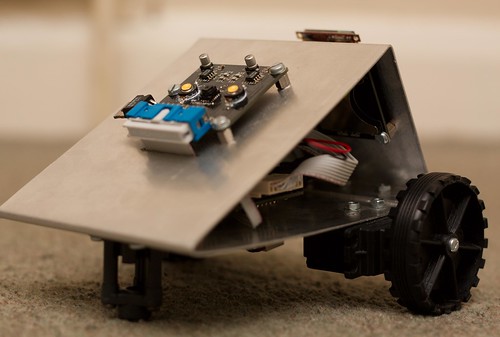
I've finally got around to writing up this project! What you see above is a small robot with a gooey ARM Cortex-M3 STM32 core, a teensy embedded camera from SparkFun, an OLED and an LCD screen, three LiPo batteries, some modified servos and a one-piece (unibody!) aluminium case. The robot uses the camera to track colour, moving towards it.
This project was actually a final year school project, so I didn't even have to pay for it, which is good - the PCBs were ordered as a panel from China, I went through several of the ARMs, and some of the other parts did not come cheap. At the end of the day, though, it works! It took a long time to get there, though...
1. Prototyping
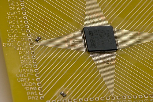
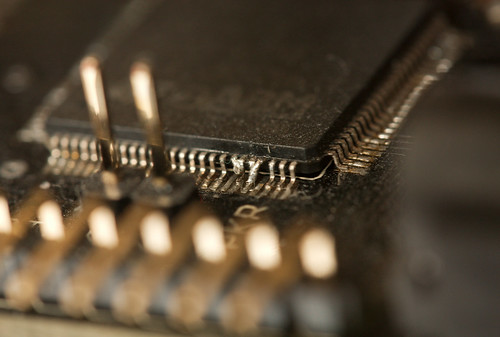
I'd never used an ARM before, which means I wanted to try one out before going for the real thing. However, I wanted to try with the chip I'd actually be using, and getting one on a premade PCB seemed like a pointless expense (how I regret thinking that...), so I made a simple breakout board and soldered one on. By hand.
Incredibly, this actually worked. It took a long time to get openocd installed and talking to the programmer (an ARM-USB-TINY from Olimex), and about as long again to actually program anything to the chip. Eventually I had that cracked and moved on to compiling my own code instead of just uploading a sample hex file. Many hours of struggling later I had a working Makefile using the Codesourcery GCC port. It was time for a more complicated Hello, World:
With this out of the way, I moved on to:
2. Design
Since this is a school project, design is important - I had to actually write this stuff up! (a 69-page A3-size Powerpoint file.) First up was schematic capture, which I did in EAGLE and involved separate designs for the main board, the camera, the OLED carrier and the SD card carrier. This is where I made a few crucial and stupid mistakes, like wiring the ARM's analog ground to Vcc and the analogue supply to GND:
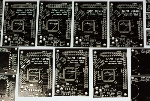
The PCB design took a few days but eventually I'd made up a design for each of the boards, and panelised these with GerbMerge to be sent off to Gold Pheonix. I even got to pick black soldermask!
The case design, while straightforward, was fun. Normally we'd use vacuum formed plastic or MDF at school, so stretching to some sheet aluminium was exciting. It's just normal aluminium with some holes drilled into it for the PCBs to mount to, though. The design was done in ProDesktop.
Schematic and PCB designs are linked at the end of the post.
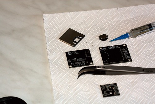
3. Manufacture
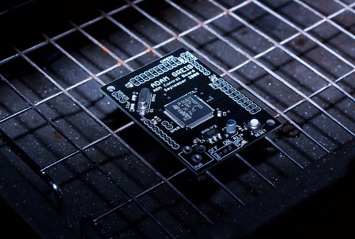
Once the PCBs and components arrived I decided to try out reflow soldering, instead of just hand soldering all these components. It worked really well - I got some solder paste, put a little blob on each pad, placed the components and then shoved it under the grill on full heat until it reflowed.
In the end I used up every one of the control boards until I finally got it right at the end - there were a few problems with the reflow soldering after someone moved the tray down one position to grill a steak (and yes, I've heard all the steak and chips jokes :P) and that threw off a few boards. The required fix for the swapped AVcc/AGND pins on the ARM wasted a few more. In the end, I got one right and that's the one that's now in the robot.
4. Programming
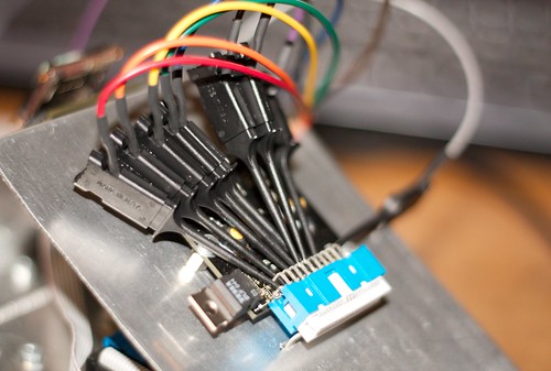
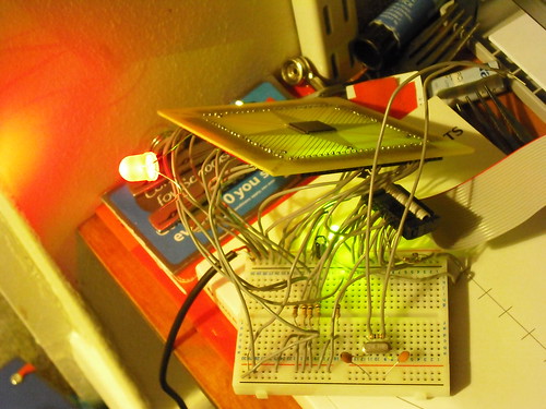
Programming this thing essentially involved an awful lot of C calling the libraries that ST provide and a bit of assembler for that speed-critical reading data from the camera. This part took ages to develop, as the camera basically just sends data as fast as it pleases and there's no simple way to manage this when your microchip has less RAM than one image from the camera. I ended up getting a logic analyser to help out, and was soon able to pick out what the camera was sending:
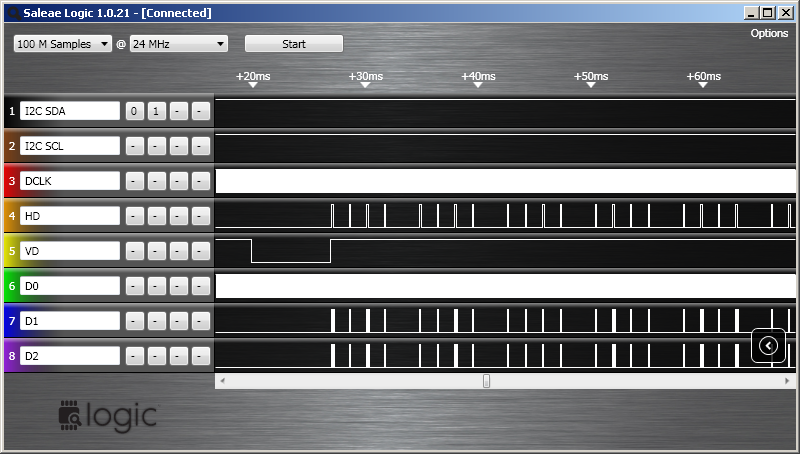
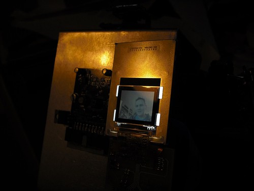
I was trying to see what the camera was showing, but this was really difficult to accomplish - there was no way to send data to the OLED screen fast enough, and no way to store the entire image in memory. I suddenly realised I could use one of the tiny LCDs from SparkFun - they work over SPI, which I'd already broken out for an SD card (that ended up unusued), and they even took the same data format the camera was sending! They turned out to be absolutely perfect for the job. All I had to do was read in each line of data, store it in memory, then trigger the DMA controller to copy that out over the SPI port. It only took a few lines of assembler and suddenly the LCD was showing exactly what the camera sent. Perfect!
From there I was quickly able to add the colour tracking part - for each pixel, it checked if it was close enough to red, and if so it used a simple centre-of-mass calculation to determine the average red position in the camera's field of view. This technique worked pretty well.
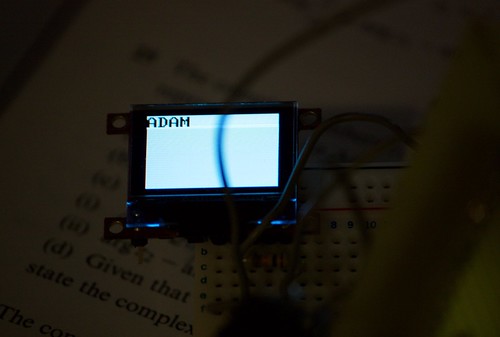
I added a simple menu on the OLED - you can toggle turning, driving and lights.

The nav switch is a handy little SparkFun switch that works really well for this application.
5. Summary
There was a lot more to this thing's development - like how to route power from 3 batteries to the two servos and the main logic, making the small breakout PCB for the LCD that included its own vreg and some status LEDs, endless cursing of various bits and pieces of the build environment, trying to affix two servos to a flat piece of aluminium and playing with supporting FAT on the SD card (harder than it might appear), to name just a few. Talking about all of them would take forever, though, so instead I've written what I hope is a more interesting to read summary.
6. Resources
The C/ASM code is available on GitHub: http://github.com/adamgreig/followingrobot which includes the build environment, makefile, etc etc. This might be pretty useful if you were trying to program one of these chips.
The EAGLE sch/brd files are available here: https://randomskk.net/projects/robot2/robot2_eagle.zip which also includes the SparkFun LCD breakout board and footprint, which could come in handy.
If you're really interested, the humangous PPT that contains a lot more detail on pretty much every stage of making this thing, as well as more photographs and logic traces and such (and also a few boring waffle pages I have to include) is available here: https://randomskk.net/projects/robot2/robot2_coursework.ppt
Finally, here's the Flickr photo set: http://www.flickr.com/photos/randomskk/sets/72157607851550306/
Please do post a comment if you have any questions!
And just to whet your appetite: the nixie clock PCBs have been sent off for manufacture and all the components have arrived! I should have a writeup of that in a few weeks once it's all been put together.