IPython Notebook Test
IPython Notebook and Pelican integration test
more ...
So it's been over a year since I posted about that NERF turret! I've not been totally idle since but nothing's really finished to a high enough standard to blog about. Instead, here's a post of almost-finished projects, crushed dreams and lost hopes!
July 2010: I ...
more ...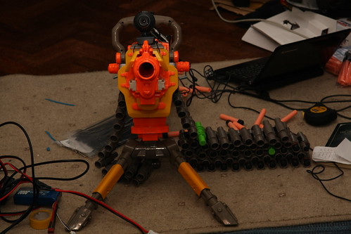
So, exams are finally over and I've had time to get playing with something again. Some friends bought me a NERF Vulcan for my birthday (cheers!) and of course I had to mod it up. The gun itself is now running off a 3-cell lipo pack, which about doubles ...
more ...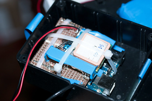
I'm part of CU Spaceflight, and since we have clearance to launch high altitude balloons from a few nearby locations we often do launches for other people. A lot of the time these launches have a radio transmitter on board, so that people around the country can pick up ...
more ...Hurrah! The laser cut acrylic for my NIXIE tube clock casearrived this morning, and amazingly all the parts fit together nicely. The screw holes even matched up with the PCBs!
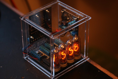
I'm pretty happy with how this turned out, and I can finally say the nixie clock project is ...
more ...As briefly mentioned in my last post, my next project is an autonomous quadcopter. That is, a four-rotored flying robot.
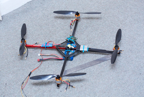
After a couple of weeks of waiting around, I've got all the parts I've ordered so far: a basic aluminium chasis from MikroKopter, four 1040Kv/14A brushless motors ...
more ...I found an old RC car - the kind of thing you get for £5 from Argos - lying in my cupboard, mostly untouched since I got it as a birthday present. Still, it has wheels and motors, what more could you ask for?
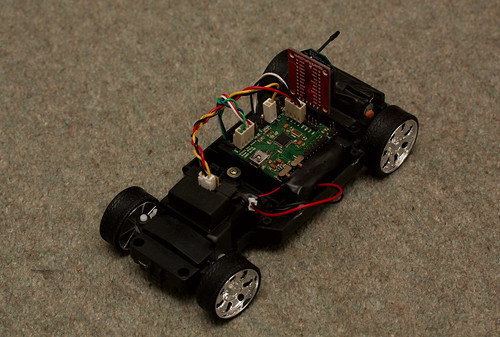
I proceeded to rip out all its electronics ...
more ...While I don't consider the clock entirely finished, I think it's been around for long enough to write up.
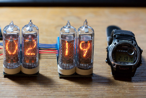
Everyone has to make a nixie clock at some time, and as I had 12 IN-14 type tubes lying around for quite a while after ordering them from Russia ...
more ...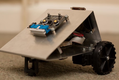
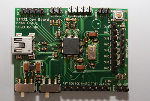
I've finally got around to writing up this project! What you see above is a small robot with a gooey ARM Cortex-M3 STM32 core, a teensy embedded camera from SparkFun, an OLED and an LCD screen, three LiPo batteries, some modified servos and a one-piece (unibody!) aluminium case. The ...
more ...