While I don't consider the clock entirely finished, I think it's been around for long enough to write up.
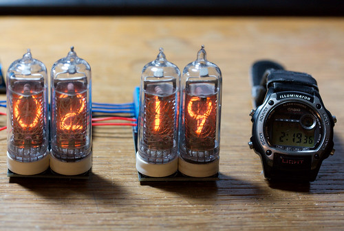
Everyone has to make a nixie clock at some time, and as I had 12 IN-14 type tubes lying around for quite a while after ordering them from Russia, I decided I should go ahead and make one. PCBs were designed in due course and sent off to Gold Phoenix for manufacture, and eventually I got back a whole load of PCBs and fabbed up the clock.
There are three main parts: the power supply unit, the control board, and one driver board per two nixie tubes.
Power Supply
I borrowed heavily from
http://desmith.net/NMdS/Electronics/NixiePSU.html in both the schematic
and PCB layout, as I don't have much experience in fast or high voltage
layout and didn't want to make any crucial mistakes. I did make a few
modifications to suit what components I could get and in a few cases
routings I thought could reduce via count or otherwise shorten traces.
The design works very well, and successfully drives the nixies at
sufficient brightness.
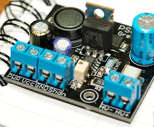
The power supply takes around 12V DC input and converts it to around 220V DC output in a switch mode design. Essentially, the microchip opens the FET, current flows through the inductor and then through the FET to ground, then the FET closes. As the current in the inductor still has a kind of 'momentum' (the magnetic field it created tries to keep the current moving) but nowhere to go the voltage rises and goes through the fast diode to charge the capacitor. Once the voltage reaches the desired level, the FET is switched back to ground again and the process repeats. The output is a relatively smooth DC. (NB: this description could be very wrong, it's just how I believe it works - please leave a comment to correct me!)
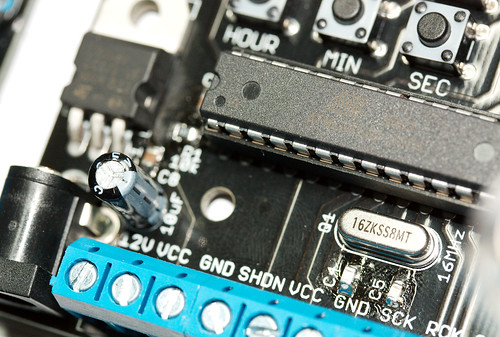
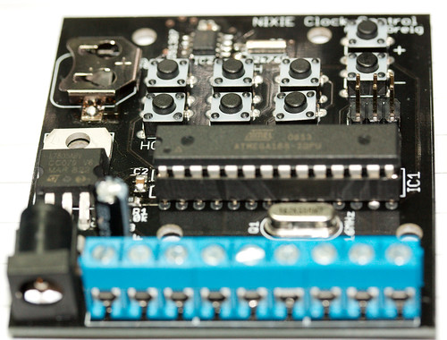
Control
The control PCB contains an ATmega168, the DS1307 real time clock IC
and a whole load of buttons used for setting the time. The RTC IC is set
with a time once and then keeps it as accurately as it can, using the
onboard battery backup to provide a tiny amount of power when the mains
electricity is removed. The buttons make setting the time fairly easy;
you just hold down the time item you want to change
(hour/min/sec/day/month/year) and press the up or down button to adjust,
holding it down to make large changes.
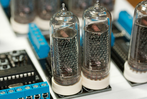
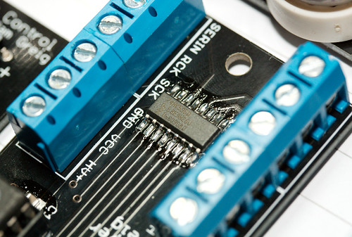
Driver
The driver PCB contains two nixie tubes, two old 7414N logic chips
(actually I used Russian equivalents) and an 8bit shift register. The
control board shifts out BCD (binary coded decimal) to the shift
registers, four bits per display digit. The shift registers then output
this to the 7414Ns which decode it and pull one of their ten outputs to
ground. That output is connected to one of the numerals in the nixie
tube, causing it to light up.
Overall, I've found it to be a really neat clock. I plan to make a nice case for it at some point in the future, but making nice cases is not a strong point for me, so I'm not sure when exactly this will happen. For the moment, the clock sits on a shelf next to my desk where I can easily see it from anywhere in the room. The digits are bright enough to see clearly, but the clock turns off the display between 00:00 and 07:00 so I can get to sleep! Turning off the tubes also helps extend their lifetime. Just before turnoff, each tube cycles through all of its digits for a few minutes to prevent cathode poisoning, where little emissions from lit numbers coat the unlit numbers and make them dimmer. Finally, clock accuracy leaves a little to be desired - it is routinely out by a minute or two every couple of weeks. It is easy to adjust and a minute isn't that big a deal, but I would have hoped the crystal would be more accurate.
At the end of the day though, it's a fun clock and is my favourite for checking the time!
All the Eagle files as well as PNGs of the PCBs are available here: [https://randomskk.net/projects/nixie_clock][] and more photos are available on Flickr here.