A while ago, I got an LED matrix from SparkFun, and soon had it rigged up on a breadboard:
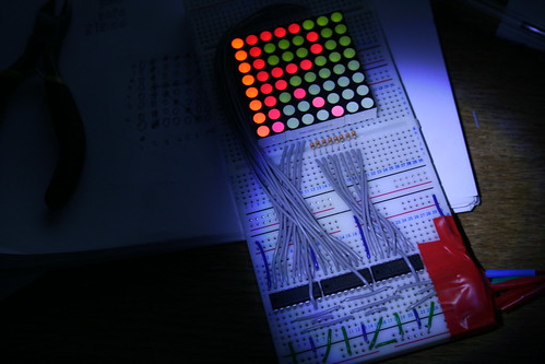
It could scroll any text I wanted, specified as a char array in the code. I had it working fairly well and decided to make a PCB for it...
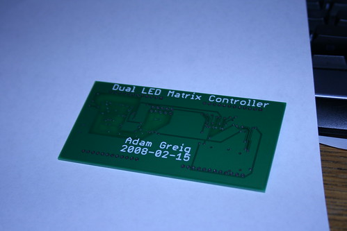
A month or so later, the PCB arrived from BatchPCB:
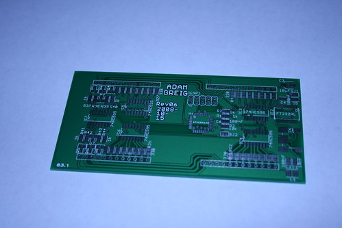
I soldered it together pronto:
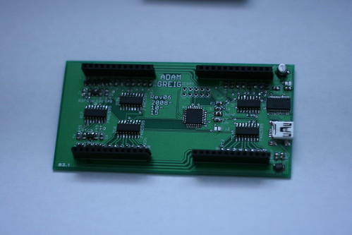
The resistors were a pain because there were so many, and the FT232RL was a pain because the pitch is so small, but overall I had no major problems and everything came together quickly.
PCB with an LED matrix plugged in:
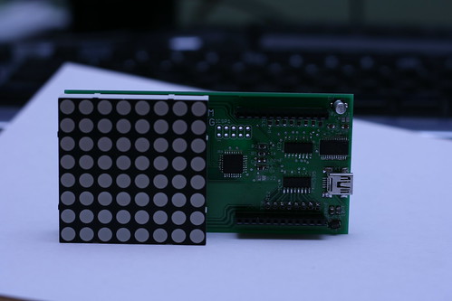
Sadly I only have one LED matrix and SparkFun are all sold out of the medium sized RG ones; I've not been able to find them anywhere else either. While I wait for them to get back in stock, I'll just work with one.
I was able to burn the Arduino bootloader code to the ATmega168 over the 10pin ICSP, and that worked fine, but then I ran into a few issues.
The first, and most prominent, was that every LED in a column lit up faintly when any of them were on. It turns out that this is because while my previous design had the cathodes connected to the shift register directly, the new design has transistors that pull the cathodes to ground. This means I have to write the shift register HIGH to get a low on the cathode. This was a an easy swap in the code.
The next problem was that the tops of each matrix were flipped over -
row 4 appeared on row 1, row 3 on row 2, etc. This turns out to have
been a problem in my circuit symbol for the LED matrix, I had the bottom
4 cathodes labelled backwards. Whoops!
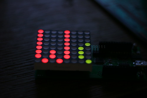
Luckily this was easy to fix in software, so I soon had it all working:
However, this wasn't the end of my issues. The ATmega168 is running at 12MHz from the FT232RL instead of using a seperate crystal and caps. However, the Arduino library expects the chip to be running at 16MHz, so all the serial timings are completely thrown off.
Luckily the ICSP header allows me to program it anyway, and this fits on next to the matrix, so it's not a massive problem. This does mean that the computer can't talk to the Arduino easily, however, which will make controlling it later a pain.
A bit of playing around in the software for the Arduino and I found a few defines I can set to get the Serial commands to run at 12MHz. This worked fairly well, I managed to get strings from the Arduino to the computer. All that's left now is getting it working the other way, and ideally getting programming it to work.
I may make another PCB that is only through-the-hole and so easy to solder, using tinyUSB and just one matrix, possibly having them connect together. I could probably release this as a kit or similar, so watch this space!