Mother's Day was coming up and I'd just got the hang of making PCBs at
home, along with a new Dremel that could cut and drill them.
Making some kind of project seemed the obvious answer. I took
inspiration from an Instructable on a similar subject here, but
didn't have any fluorescent acrylic so had the LEDs illuminate the board
directly.
It's also etched with normal ferric chloride, unfortunately.
I'd just picked up some new surface mount button-cell holders, and while I was tempted to use a 555 to make a quick pulse that drives the LEDs, a simpler circuit could be made with an ATtiny13, and I just so happened to have ten of them sitting around. A little breadboarding and I'd got the general idea working, although PWM still wasn't working - the LEDs simply flashed on and then off 12 seconds later, with no fading.
I documented most of the manufacture with my camera, so I'll go through it with pictures. Here goes...
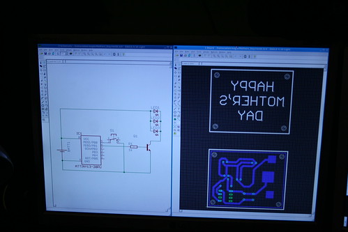
First, the circuit had to be designed. I do this in Eagle, since it's free and runs on Linux. The design has to be single sided (I've only got single sided boards, for one thing), and I figured the thicker tracks would make it more resistant to any problems with the toner transfer. It didn't take too long to come up with an acceptable design that doesn't have any jumper wires.
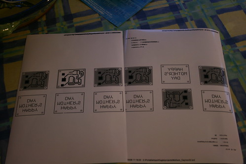
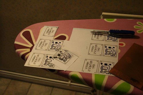
Next, I tried using photo paper to print and transfer the toner. This
basically failed miserably - the paper got too hot before the toner was
too hot, and the paper bubbled up underneath, ruining it. I tried all
six circuits that I printed and none worked.
However, the photos showing the manufacture are the same as for
transparencies, so I'll go through them anyway.
[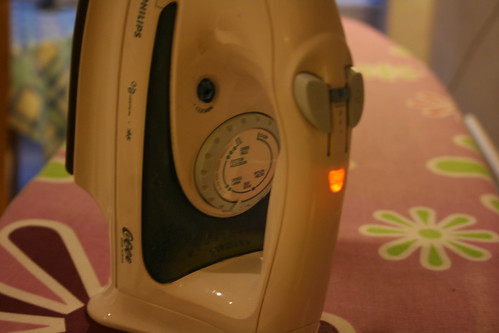
The iron's heated up to "Wool" for transparencies
Boards are scrubbed clean with a scrubber and also rinsed, I didn't bother with soap later on and it worked fine. Faux-steel brushes would probably be even better, or perhaps sandpaper. The key thing is to get a clean copper surface that's slightly scratched up to help the toner stick.
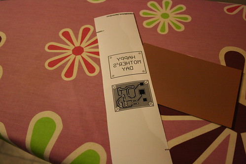
The chosen design is cut out.
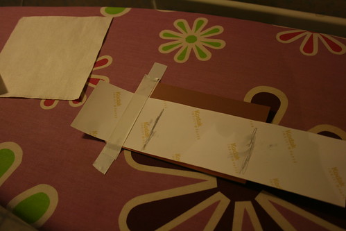
And stuck down to the board, toner side down.
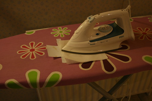
You then put tissue paper over it to stop the iron sticking to the paper, and heat it for \~5min.

Sadly, every try with photo paper came out pretty badly.
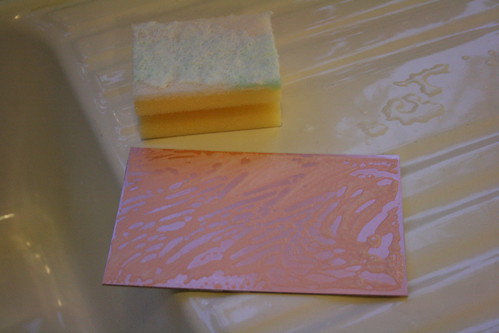
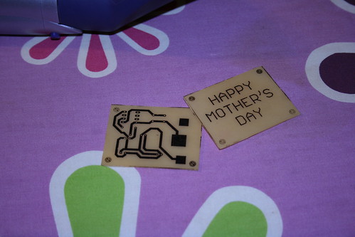
I got some transparencies printed. These worked a lot better!

Transparency is stuck toner-side down. You can tell which way this is because the circuit should look the right way around when the transfer is stuck down.
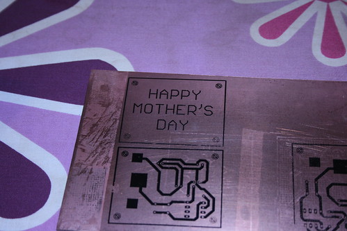
It did take a second try to get the temperature right, but this is much
better!
There are still one or two small issues - nothing that stops the board
working, but a few tracks lost a little toner. This is easily fixed with
a standard permanent marker.
I cut out the PCBs using a cutting disk on the Dremel (in this case the
one-clic cutting disks which I believe are fibreglass-reinforced ones).
This wasn't too easy since the edge of the dremel somewhat restricts how
deep the cut can be into the material, but I was just able to get them
both cut out nicely.
Then I sanded them down at the edges to make them nice and smooth.
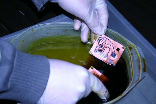
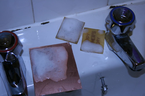
I then etched both boards in ferric chloride. This is a fairly poor, but
easily available etchant that doesn't give off nasty fumes. It does
stain everything, so I'm wearing gloves here. I have a plastic tray of
etchant placed in a larger plastic tray of hot water, which heats the
etchant and catches any spills. I constantly swirl the board around in
the etchant, which makes a big difference in etching time.
In this photo, you can just see the copper starting to be etched away
in the corners.
The boards are now fully etched, the only copper left is hopefully under
the toner!
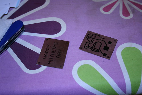
The toner is non conductive and can't be soldered to, so we need to
strip it off the copper tracks.
I usually let the boards soak in acetone for ten minutes and then scrub
hard to remove the toner. I'm also removing the toner from the
non-etched board so it can be reused.
In retrospect, I noticed a few things:
1) There really wasn't any need to remove toner from the top PCB, since
it won't be soldered to and toner may have even made the sign stand out
better. However, the copper does look fairly nice.
2) Toner could also be used as something of a solder stop, so
potentially I could have only removed it from pads that had to be
soldered too. This may have been risky later on with the copper heating
up, though.
3) Paint stripper probably would have worked better.
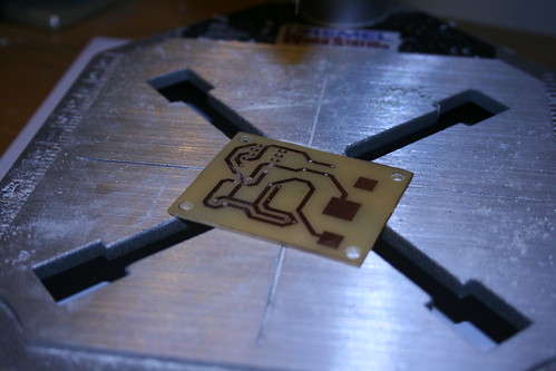
The PCBs are then drilled: a 3mm hole for the 4-40 thread screws, and 0.8mm holes for everything else. I'm using HSS drill bits in my Dremel at 33k RPM, the boards are FR2 so there's not so much need for tungsten carbide drill bits.
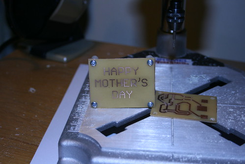
Both boards are now drilled.
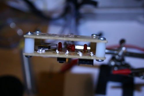
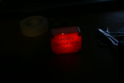
Components get soldered on. Soldering the LEDs was a real pain, but luckily you can't see the solder when the thing is closed up. In the future, I'd probably use surface mounted LEDs. The battery holder doesn't seem to fit the batteries very well, so I use two batteries instead - this is not only a much better contact, but also drives up the LED's brightnesses.
I ended up using two stand-offs taped together, instead of just one, to give the LEDs more space to diffuse. This made a big difference. It also let me cover the outsides with tape, which makes the whole thing look a lot more solid.
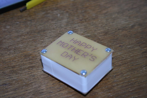
Finally, here it is in all its glory!
The ATtiny13 has a fairly simple program that just turns on the LEDs through a transistor for 12s when the button is pressed, and goes to sleep (power-down mode) otherwise. I wanted to have the LEDs fade in and out using PWM, but I wasn't able to figure out how to do proper PWM with the IC's counters in time, and software PWM took up too much space when the code was compiled, for some reason. Having some kind of on/off mode might have been a neat idea too, although this way the two batteries should last a lot longer.
I hope you enjoyed reading through the project! I've attached the Eagle files below if anyone wants to try printing one, although since Mother's Day has passed I'd suggest changing the message :p